New links
Balaji Polymers TPR soleWith the commissioning of the new TPR sole line, Balaji's installed a capacity is expected to double to 30,000 pairs per day by July 2010 and make it the 2nd biggest
TPR sole manufacturer in India
TPR Shoe Sole manufacturer India
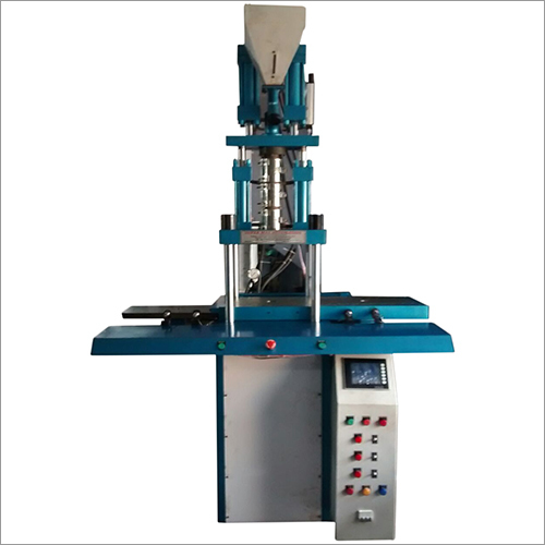
Plastic injection molding machine, BALAJI AUTOMOTIVE, Delhi
Industrial Machine
We manufacture industrial machines such as molding machine and die cutting machine. Our products are well designed and tested for years of trouble free service. Our plastic injection moulding machines are manufactured with the best available raw material in market which provides longer service life
Contact Details Balaji Automotive We provide a wide range of durable vertical plastic injection molding machines that are known for quality, reliability and efficient performance. Used in various industries these are backed by latest technologies and also feature user friendly PLC (
programmable logic controller) operating console. These machines can also be customized as per clients' specifications.
Features: - Fast in operation
- With hydraulic injection & locking
- Specially used for okward die & insert molding
- Touch Screen based controls
- Digital display
- Electronic control of clamp force, speed & heat
- Digital PID temperature controllers
- Safety guards and access doors
- Thermic fluid heated plates
- Bottom hydraulic core lifters
Cities:Delhi, Faridabad, Gurgaon, Noida, Mumbai, Ahmedabad, Chennai, Hyderabad, Bangalore, Kolkata, Kochi, Gwalior, Agra, Lucknow, Kanpur etc.
Description/ Specification of Horizontal Moulding Machine We also offer horizontal molding machines that are precision engineered as well as are highly user friendly. The machines are designed by experts and undergo stringent quality checks that ensure in them optimum performance standards. These can also customized as per client's configurations and are available in competitive prices.
Features:
* Hydraulic motor mold height adjustment
* Low protection mold safety
* Hard Chrome Plated High Tensile Steel Tie Bars
* Centralized auto Lubrication System
* Hydraulic Oil High Temperature Alarm
* Fully managed by a software and a micro controller
Cities:Delhi, Faridabad, Gurgaon, Noida, Mumbai, Ahmedabad, Chennai, Hyderabad, Bangalore, Kolkata, Kochi, Gwalior, Agra, Lucknow, Kanpur, Bahadurgarh, etc.
next site:adi dharamprevious site:
http://sites.google.com/site/plcprogrammablelogiccontroller/
Fighting PID's
We have the ML1400, 1762-IF4 and 1762-OF4 modules. The system consists of one pump supplying 2 water systems. Each system has a flowmeter and a modulating valve. The flow is to be split 50/50 thru each system. The PID's are set up to take half the desired flow and adjust the modulating valve to achieve this. One issue is they are butterfly valves and at the desired flow being 10-20 % open, rather than the desired mid range at desired flow. I'm not sure of the valve resolution at the low end of the valve. (I'm not a valve guy)
I haven't been to the site yet, the customer reports the PID's the unit will "hunt" with a large range. Never stabilizing near the set point. I understand PID tuning is more of an art than science. To me this is a "P" system not needing the I or D. Question: What would be good starting parameters for the gain, and loop update? Do we need a larger (than 0) deadband to allow the system to stabilize?
How do we make these guys quit fighting?
Thanks in advance! |
| djs (Electrical) | 12 Mar 10 12:51 | You might never be able to make the system work. The issue is your actuator gain is too high. In other words the valve at 10% open when at operating setpoint. This means your valve gain is nearly 10. Most valves have a hysteresis of 1 to 2% which is 10 to 10% of your setpoint. In other words the closest you will be able to come to matching flows is +- 20%! | |
| cjw32 (Nuclear) | 17 Mar 10 5:11 | Hi, Sounds like you have the system responding far too quickly because your proportional gain is far too high for the characteristics of the valve. Have you tried ziegler-nichols loop tuning? It gives a good starting point from which you can then fine tune the loop. We have valves that operate at around 25% to 30% for flow control and it works perfectly. We deliberately chose an over-damped response as our system is chemically very sensititive to sudden flow changes. You'll need to check the flow characteristics of the exact valve you've installed but for a generic butterfly valve you're flow is relative to the position so you're operating at 10-20% of flow so sounds like you've oversized the valves. To be honest, I would start with a low proportional gain and a little integral to get an overdamped response. You'll need to check the speicific set-up for the PID controller as a lower I setting usually means a higher frequency of intgrating the error and therefore a faster response, so you might want to set the I setting higher. Once you have an overdamped response you can start increasing the P to speed up the initial response (but if you're operating at the lower end of the valve then I'd probably keep the P value low). I'd then start decreasing the I to increase the valve response. But again there are so many factors to take into account, such as the dead-time response, that it's hard to give specifics. I would also look at the equation for the PID controller you have as well as that will give you an idea of how it will respond. | |
XG5000 and Mod bus Command
Oh your help and knowledge is really useful. Thanks so much!Yes, it is Modbus ASCII that I am using. Right now I have both PID and PLC setting to 8-bit character set. So I am going off the standard I guess. Btw if you set to 7, does that mean that, for example, 33 will go as 011 0011? I guess it works cause ASCII only has 4's and 3's as the high portion of the byte...
Regarding the hyperterminal, you mentioned checking the 1000H address. That is a fantastic idea but in their manuals I know also that 1000H is the address of PV. Also, I would require an RS 485 to USB converter to hook up to PC and do it and I don't think I want to get that...
Since the RS 485 is between PLC and PID, right now, I just want to have a way to monitor the communication...but the problem is I do not see anything in the PLC software (XG5000) nor in the manuals regarding where to initiate the communication from or what command/function can be added to the ladder logic so that for example when a switch is triggered the PLC issue a command.
Again I really appreciate your time and consideration.
The problem with the wrong word size (7 vs 8 bits) is how the serial ports on either handle the data words. It might just work out at 8bits/word. It's worth a try.
Sorry I can't help you on the PLC specifics, I'm just a generic Modbus guy (HMI, SCADA, OPC mostly).
Modbus, until only recently, has been an option on most PLCs, (now it's standard on only a few of the hundreds of models available), so it isn't surprising that you're not finding information on dealing with Modbus for you particular model. PLCs have at least one, sometimes multiple serial ports, but whether Modbus functionality is implemented is firmware/hardware based.
Check with the manufacturer to see what they have to say about Modbus.
Good luck.
Dan
http://smxplc.com/
XG5000 and Mod bus Command
Thanks so much for your invaluable input.
Please find attached the image file pertaining to a read command of Process Value from a PID controller (please zoom in to see everything). Here is a link in case it is not attached:
http://files.engineering.com/getfile.aspx?folder=376da431-5e34-4b23-a89d-74411b920d8b&file=file.bmp I converted character by character:
Start of Tx ':' -> 3A
Address if unit 1 and address of unit 2 ( I am not sure whether you combine them or you have to have an ascii for each char, please look at the char. Why do we have address if unit 1 and unit 0 ? 0:
01 -> 31 or you could say 0 1 --> 30 31
Command 1 and Command 2 : 03 -> 33 or 0 3 -> 30 33 (read)
Starting address: 10 00 -> 4130 or 1 0 0 0 -> 31 30 30 30
....
so what do you think?
As for the PID controller, yes, it does accept ASCII protocol in the settings.
Should ASCII data length be 7 or 8? I get both numbers mentioned in different articles and it is confusing a bit.
Now as for sending the message, you have a good point. I have to ask the PLC manufacturer about the s/w utilities that make it work.
Thanks again for your care to educate people. I really look forward to your response.
Boy, that protocol example you provided sure looks like Modbus ASCII to me . . . The example shows you the characters that you would type on the keyboard when using HyperTerminal. HyperTerminal then converts what you type to ASCII for transmission via the serial port.
So the characters in the example have to be converted to ASCII (as you've done) in your routine, unless you're using a terminal tool like Hyperterminal.
Start of Tx ':' -> 3A
Ans: That's correct. Colon is the Modbus ASCII start character.
>Address if unit 1 and address of unit 2 ( I am not sure whether you combine them or you have to have an ascii for each char, please look at the char. Why do we have address if unit 1 and unit 0 ?
Ans: You're suffering from a bad manual writer or maybe a bad translation from Japanese.
There is only a single address composed of two characters.
The address should be:
high order address character, then low order address character.
In the Omron example the slave address was 01, so
high order character = 0, low order character = 1.
The Modbus format requires both characters for the address, so for an address of 01h,
Modbus ASCII would use 30 31 ASCII
Same holds true with the function command, both ASCII characters are needed.
Modbus function command 03h is the most commonly used function: 'read holding registers'.
High order character = 0, low order character = 3.
So the command read holding register, 03h, would translate to 30 33 (ASCII)
> Command 1 and Command 2 : 03 -> 33 or 0 3 -> 30 33 (read)
Ans: You are correct.
So far the message reads (the forum formatting will screw up the columns)
: 0 1 0 3
ASCII: 3A 30 31 30 33
> Starting address: 10 00 -> 4130 or 1 0 0 0 -> 31 30 30 30
Let's assume that the example is correct & works, so that the address for the PV is at 1000h.
(you might want to examine the Modbus map and confirm that the PV is really at 1000h. In fact you might want to fire up Hyperterminal, get a 'read' and see if the PV is really at 1000)
The address is 2 bytes, or 4 characters in hex, 4 characters in ASCII
The conversion to Modbus ASCII is 31 30 30 30, like you proposed.
: 0 1 0 3 1 0 0 0
ASCII: 3A 30 31 30 33 31 30 30 30
Now you have to define how many registers are to be read. If you only want the single value then one value = 0001h or 30 30 30 31 ASCII
: 0 1 0 3 1 0 0 0 0 0 0 1
ASCII: 3A 30 31 30 33 31 30 30 30 30 30 30 31
> Should ASCII data length be 7 or 8? I get both numbers mentioned in different articles and it is confusing a bit.
Ans: Modbus ASCII, by the Standard, is a 7 bit data word.
Modbus RTU is an 8 bit data word. This protocol is clearly Modbus ASCII.
http://smxplc.com/
XG5000 and Mod bus Command
I would like to solve the following problem:
A LSIS
PLC needs to talk to PID controller over RS 485 and Modbus (PLC master - PID slave)
LSIS XG5000 software interacts with
PLC manufacturer.
But the problem I have is that I do not know where in the
PLC I can put the ASCII commands to send to the PID.
From the manuals I have read, so far I am able to set up both the cnet interface of the PLC and the PID controller to have the same settings (baud rate, parity, etc).
The only other thing I can think of right now is that the
modbus settings in the PLC software (XG5000 provides a bit and word address range: like word read is p06, word write is p070, etc....
Side note: In ModBus ASCII, I need to put:
address unit 1 | address unit 2 | Command 1 | Command 0 | ....|End1|End2
Here the string to read the process value of the PID. It starts with ASCII character ':' (3A) and ends with 'CR LF' (0D 0A). Everything in the middle is the protocol definition like address of who receives this, what to do (read/write) and etc.
3A 31 30 33 31 30 30 30 30 30 30 31 45 42 43 0D 0A
Note that code has the beginning 3A which is ':' character indicating beginning of ASCII frame. CR and LF (0D 0A) mark the end.
Let's talk generalities, rather than specifics. If you need to talk either Modbus RTU or Modbus ASCII, you typically have go back to the PLC manufacturer and ask, "what hardware/firmware/software do you have to talk Modbus RTU or Modbus ASCII?" and procure whatever that is i order to implement Modbus on a PLC.
If your PLC doesn't talk Modbus in any form, but talks some other serial protocol, there are commercially available gateway boxes that can be programmed to talk serial on one side and Modbus on the other to do protocol conversions.
Frankly, I'd be surprised if your Omega controller actually talks Modbus ASCII. Does the spec/manual say "Modbus ASCII"?
I suspect it talks the Modbus RTU protocol. Very few commercial PID controllers nowadays talk Modbus ASCII.
Modbus ASCII is a derivative of Modbus RTU without some of Modbus RTU's critical timing requirements, the trade off being a halving of the effective data transfer rate, since RTU transmits binary values, whereas ASCII transmits the two hex values of an 8 bit byte literally as ASCII characters, doubling the amount of bytes for the same information/data.
You mention a 'cnet interface', which is a total unknown to me.
http://smxplc.com/